Through the analysis of changing patterns among different anaglyphic images and the relationship of their focal planes, this paper first derives a way to measure the stereoscopic effect of an image. By using statistical analysis, an empirical value of stereoscopic effect is then defined. Based on the principles of photographic camera in 5 different scenarios, the author infers that the stereoscopic effect formula derived are suitable for mid and long range photography. With some simple assumption and approximation, the formula can also be extended to short distance and micro distance photography. The suitability and the impact of the parameters are then further discussed. All the topic discussed in this paper are applicable to 3D effect on lenticular printing.
Anaglyphic Image is one of the methods for displaying stereoscopic picture. It is based on the principle that red and blue are complementary colors. It is created by using a software tool to combine the left and the right image into a single picture. By looking at an anaglyphic image with an anaglyphic viewer (also called Red and Blue glasses), our left eye will see the red-colored left picture and the right eye will see the blue-colored right picture. Our brain in turn makes them into a stereoscopic picture.
Lenticular printing on the other hand does not require any external visual aid or devices to see stereoscopic images.
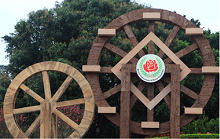
The stereoscopic effect of an image is created by the depth of foreground and background in a view. A 2D image on a piece of paper cannot have a stereoscopic effect. From presentation point of view a stereoscopic image is superior to a flat image. For example, Figure 1 is not as spectacular as those anaglyphic pictures in Figure 2 to 6. In a scene, it usually includes three sections; i.e., the foreground, the mid-ground, and the background. (In this article, the foreground means the most frontal portion of a scene and the background is the farthest end of a scene. The mid-ground is anywhere between the foreground and the background). For example, in Figure 1, the smaller wheel on the left is the foreground, the bigger wheel on the right is the mid-ground, and the trees in the back constitute the background.
Please proceed with a pair of RED / BLUE glasses to view the following analyphic images.
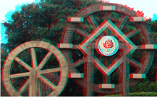
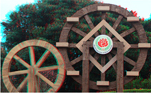
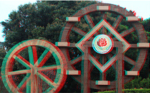
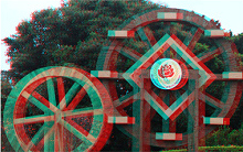
Stereoscopic image has an important concept: focal plane. It is a 0 thickness plane that intersects vertically with the depth. In an anaglyphic image, the position of the focal plane is in an area where the red and blue images coincide completely. In other words, it is an area where there is no red and blue image. If the focal plane is a window, the objects in front of the focal plane look like they are outside the window. The objects behind the focal plane look like they are inside the window. In Figure 4, the position of the focal plane is on the bigger wheel. Thus, the smaller wheel in the front is outside the window and the trees in the back are inside the window. When you use Photoshop to merge the right and the left image into a anaglyphic image, assuming the right image is static and you are only moving the red left image from left to right, you will notice the window gradually moves from the front to the back in an order seen in Figure 2 to Figure 6.
How do we use anaglyphic image to measure stereoscopic effect? We know from the anaglyphic image where stereoscopic effect is shown as double image. Specifically, the stereoscopic effect is the degree of horizontal deviation between red and blue image. Take Figure 3 as an example, the small wooden wheel in the foreground doesn’t have double image thus it is the position of the focal plane. The large wooden wheel in the mid-ground has double image. There is a horizontal deviation in both red and blue image. The double image also occurs in the background which has an even bigger horizontal deviation. The largest horizontal deviation in the background reflects the degree of stereoscopic effect. When the deviation becomes too large, our eyes become irritated. If the horizontal deviation is too small, the stereoscopic effect becomes insufficient. Naturally, the size of horizontal deviation is closely related to the size of the image itself. Therefore, we define the formula for a stereoscopic effect as a ration between an anaglyphic image’s maximum level of deviation and an image’s horizontal distance. It can be expressed as:
$$ c = \frac{δ}{r} 100\% ---------- (1)$$
Where c is the stereoscopic effect, δ is the maximum level of horizontal deviation, and r is the image’s horizontal distance.
In this formula, the denominator of r which is the image’s horizontal distance, can be easily measured. We only need to get a ruler to measure either on a computer screen or on a picture. On the other hand, to measure the numerator δ (the maximum level of an anaglyphic image’s horizontal deviation) will not be as easy. There are 5 different conditions to consider:
It is not difficult to discover that maximum level of horizontal deviation is based on the horizontal deviations of the foreground and the background and the direction of the horizontal deviation. It is a plus when the focal plane is in the mid-ground otherwise it is a minus.
Thus, the maximum level of horizontal deviation can be concluded as the horizontal deviation difference between the foreground and the background. The table below shows the measurements of Figure 2 to Figure 6 and their values of stereoscopic effect.
| Foreground Deviation (mm) | Background Deviation (mm) | Maximum deviation δ (mm) | |
| Figure 2 | 2 | 10 | 8 |
| Figure 3 | 0 | 8 | 8 |
| Figure 4 | -2 | 6 | 8 |
| Figure 5 | -8 | 0 | 8 |
| Figure 6 | -10 | -2 | 8 |
| $$ r = 237mm\;\;\;c = \frac{δ}{r} 100\% = \frac{8}{237} = 3.4\% $$ | |||
The author has collected more than 40 high quality anaglyphic images from the Internet. Based on the above mentioned methods, the author measured these images on computer screen and calculated the values of their stereoscopic effect. The results of statistical analysis, almost all the images’ stereoscopic effect values are between 1% and 4% with the average value at 2.5%.
$$ c = 2.5\% ± 1.5\% $$
It was found during the process of statistical analysis that for those images with a very large depth (e.g, long streets), their stereoscopic effect values are greater. Likewise, the images with a shallower depth (e.g. portraits,) their stereoscopic effect values are smaller. This coincides with the stereoscopic effect formula inferred below.
Due to the limited statistical sampling, these values might not be exactly accurate. However, they possess certain reference value. Accuracy of these values relies on higher samples numbers and the image.
In the Stereoscopic Effect formulas, we need to determine two variables, namely the horizontal distance r and the horizontal deviation δ. First, let’s look at how to calculate image’s horizontal distance r.
No matter how complicated a camera’s lens is, in general you can view it as a convex lens (As shown in Figure 7).
In Figure 7, α is the viewing angle of a lens, the focal length is f, the width of the photosensitive part is d (please note it is not the length of the diagonal line). The width of the object is r and the distance from the lens to the object is u. When the object’s distance is long enough from the lens, you will find r / d = u / f. Hence
$$ r = \frac{d}{f}u ----------- (2)$$
This is to say, when the width of camera's photosensitive d and lens' focal distance f have been determined, the width of the scenery r and the object’s distance u are in direct ratio.
In Figure 8, O1 and O2 are the locations of the left and the right lens. The lens axis (lens distance) is v. The lens’s viewing angle is α. M1O1N1 is the viewing area of the left lens. M2O2N2 is the viewing area of the right lens. M2ON1 is the cross section of these two lenses.
L is the distance between the lens and the foreground scenery. The distance from the lens to the background is L + S. It means S is the depth of view. A is any point in the foreground. B is any point in the background.
In this case, the horizontal deviation distance of the B point in the background is δ1 = P1Q2. Please note, the triangle P1BQ2 and triangle O1BO2 are similar. Thus Δ P1BQ2 ≈ O1BO2, thus δ1 / v = S / L + S, δ1 = vS / L + S. From formula (2) we know, r1 = (d / f) x L. We will have the stereoscopic effect formula when we plug in Δ1 and r1
$$c = \frac{vSf}{dL(L + S)} --------- (3)$$
When background is the focal plane, the horizontal deviation of A point in the foreground is δ2 = P2Q1. As shown in Figure 8. Please note, Δ P2AQ1 ~ O1AO2, thus δ2 / v = S / L + S, δ2 = vS / L + S. From formula (2) we know, r2 = d / f x (L + S). When we plug δ2 and r2 in formula (1), we get the same formula (3). Is this coincidental? Please read on.
In Figure 9, there is a focal plane line between the foreground and the background. Let’s denote X as the distance from the line to the foreground. In this case, the horizontal deviation for the A point in the foreground is P2Q1. The B point in the background is P1Q2.
The horizontal deviation of A point,$$ \triangle P_{2}AQ_{1} \sim \triangle O_{1}AO_{2},$$
hence \frac{P_{2}Q_{1}}{v} = \frac{X}{L}, P_{2}Q_{1} = \frac{vX}{L}$$The horizontal deviation of B point, $$ \triangle P{1}BQ_{2} \sim \triangle O_{1}BO_{2}, hence \frac{P_{1}Q_{2}}{v} = \frac{S - X}{L + S},\;\;P_{1}Q_{2} = \frac{v(S - X )}{L + S} $$.
The total horizontal deviation, $$ \delta_{3} = P_{1}Q_{2} + P_{2}Q_{1} = \frac{vX}{L} + \frac{v(S - X)}{L + S} = \frac{vS(L + X)}{L(L + S)} $$
From formula (2), $$ r_{3} = \frac{d}{f (L + X)} $$ Plug δ3 and r3 into formula (1), we also get the stereoscopic effect formula (3). This formula has no relationship with X.
In this case, all the objects are in front of the focal plane as shown in Figure 10. Assume the distance from the focal plane to the background is X.
The horizontal deviation of A point, $$ \triangle P_{2}AQ_{1} \sim \triangle O_{1}AO_{2}, hence \frac{P_{2}Q_{1}}{v} = \frac{S + X}{L}, P_{2}Q_{1} = \frac{v(S + X)}{L} $$
The horizontal deviation of B point, $$ \triangle P_{1}BQ_{2} \sim \triangle O_{1}BO_{2}, hence \frac{P_{1}Q_{2}}{v} = \frac{X}{L + S}, P_{1}Q_{2} = \frac{vX}{L + S} $$
The total horizontal deviation, $$ \delta_{5} = P_{2}Q_{1} - P_{1}Q_{2} = \frac{v(S +X )}{L} + \frac{S - vX}{L + S} = \frac{vS(L + S + X)}{L(L + S)} $$
From formula (2), $$r_{5}= \frac{d}{f(L + S + X)} $$. Plug δ5 and r5 into formula (1), we also get the stereoscopic effect formula (3).
One item that needs attention is that the r, the image’s horizontal distance (length) is actually a constant. It is due to lens’ perspective, we see the distance difference in r1 to r5.
The results of the 5 conditions all lead to the stereoscopic effect formula (3). In other words, an image’s stereoscopic effect is not related to relative position of the focal plane. It was decided when the picture was taken. This is the inherent characteristic of a stereoscopic image.
The formation of an image through a lens follows the rule of 1 / u + 1 / i = 1 / f where i is the image distance. When u the object distance, the distance between lens and the object is sufficiently large, i approximately equals to the focal distance f. For example, when we use a 50mm lens to take a picture of an object 5 meters away the image distance is 50.5mm. The relative error between the image distance and the focal distance is (50.5 – 50) / 50 = 1%. The longer the object distance is the smaller the relative error. In this case, image’s horizontal distance calculation formula (2) can be established. In other words, stereoscopic effect formula (3) is only suitable for mid range photography. What about short range photography?
It is actually pretty simple. If we treat the object we are taking in its entirety, the distance between the lens and foreground becomes the object distance (L = u), from the image formation formula we get i = Lf / L –f. In formula (3), we replace focal distance f with the image distance i, we get:
$$c = \frac{vSf}{d(L –f)(L + S)} ------ (4)$$
There is not much difference between formula (4) and formula (3). When L is large enough (greater than f), L - f ≈ L, formula (4) degrades to formula (3).
In micro photography, the object is very close to the lens, usually measured in few decimeters. But the depth of field is even shorter, only in few millimeters. In this situation, L is greater than S, L + S ≈ L, Formula (4) degrades to:
$$c = \frac{vSf}{dL (L - f)} ------- (5)$$
To summarize it, amongst the three stereoscopic effect formulas, formula (3) is suitable for mid range photography. Formula (4) is suitable for close range photography and formula (5) is suitable for micro photography. And formula (4) has the comprehensive nature. The other two formulas may derive from it through simplification.
The above stereoscopic effect formula is derived from anaglyph. In fact, its theory is similar to that of parallel graph and interlacing graph. The only difference is that anaglyph is more straightforward and easier to be surveyed and measured.
There was a hidden hypothesis during the process of inferring these stereoscopic effect formulas. It was assumed that the viewing field of a camera’s lens is flat. It is only reasonable in such a condition to treat focal plane as a flat plane. The actual viewing field should be spherical but the lens adjusts this spherical viewing field into a flat plane viewing field. The bigger viewing angle of a lens, the more obvious spherical plane there is. It is harder to make adjustment when a wide-angle lens is used due to barrel-like distortion. Thus these stereoscopic effect formulas are only suitable for mid and long range lens and a type of wide-angle lens that can control distortion. It is completely unsuitable for fish-eye lens.
All the parameters in the stereoscopic effect formulas are unit of length. The resultant value of stereoscopic effect is very small. The values in d, l and v are measured in mini-meter. In mid-range photography, the L and S are measured in meter which is two number magnitudes larger. In micro-range photography, The L, d, f and v are measured at the same level while the S is two number magnitudes smaller.
To see the impact of these parameters to the stereoscopic effect, we can take a look at the c, which is the value of stereoscopic effect. It will increase when the v, f, and S increase. On the other hand, it will decrease when the L and d decrease.
Each parameter has its own order. First, the camera determines the value of the d, the lens determines the value of the f, then after the scene has been selected, it determines the value of the L and S. Finally, after picture is taken, it determines the value of the v. Therefore, when taking a stereoscopic picture, the lens distance v is the most nimble and the most controllable. It is also a parameter that has the biggest impact.
In the stereoscopic effect formulas, a parameter's change will cause other parameter to change. We will analyze the impact on other parameters when the value of focal distance, the f is changed. For this analysis, we will use three scenarios in mid-range photography.
When using a 135 camera (d = 36mm) with a 50 mm standard lens for mid-range photography. The formula (3) can be simplified into $$ c = \frac{1.389 v S}{L (L + S)} $$
Then based on using the 1/50 lens distance experience, $$ \frac{v}{L} = 1/50,$$ we get $$ c = 1.389 \frac{1}{50} \frac{S}{(L + S)} = \frac{S}{(L + S)} 2.78\% < 2.78\%$$ This is to say that under such shooting condition, stereoscopic effect value shouldn’t exceed 2.78%.